Purpose of this Article #
This article describes how to take a VxWorks® bootrom that is built using the Wind River® BSP, alt_soc_gen5, combine it with a preloader built from an Altera® FPGA design, and boot the Altera Cyclone® V and Arria® V SoC development boards using QSPI or SD/MMC.
What is Needed to Build this System #
The following is needed to build this system:
- An Altera Cyclone V or Arria V SoC development board to run the software.
- A Wind River workbench development environment and license to build the VxWorks bootrom.
- An SD/MMC card to hold the boot software for SD/MMC or help program QSPI. Alternatively, you can use the Altera Quartus programmer to program QSPI instead of programming through the SD/MMC.
- The Win32 Disk Imager program to write the image to an SD/MMC card. You can also use the Linux program
dd, but be careful with the device name. You can download the Windows tool from the Sourceforge® website.
This package contains pre-built binaries to get started, including:
- Prebuilt SD/MMC images for Cyclone V and Arria V development boards.
- Prebuilt preloader images for both QSPI and SD/MMC and for both Cyclone V and Arria V development boards.
- Prebuilt version of the linux utility
mkimagefor Windows, used to wrap the VxWorks bootrom with the proper header.
This release also contains a script, make_sdimage.sh, to help create a new SD/MMC image on a linux system.
These instructions are tested with, the following:
- Altera Cyclone V SoC Revision C development board
- Wind River Workbench version 3.3.4 and VxWorks versions 6.9.3.2
- alt_soc_gen5 BSP from Wind River, version 6.9/1
- Altera SoC EDS, version 14.0
- Altera Quartus Programmer, version 14.0
- Ubuntu 12.04 LTS, running as a virtual machine on Windows using Oracle’s® VirtualBox® 4.2.6 with VBoxGuestAdditions installed to share files between Windows and Linux
The mkimage binary and all of the preloader binaries are built from GPL licensed open source software included with Altera’s SoC EDS product. This product and the source can be downloaded for free from the Altera Software Depot download page.
Related Information
Instructions on booting VxWorks #
In order to boot VxWorks, you can use these instructions to build a bootable system using a preloader and u-boot, and then replace the u-boot bootloader with a VxWorks bootrom.
- For SD/MMC boot:
- You can use the pre-built SD/MMC images to create a bootable system using u-boot in place of the VxWorks bootrom to see your board boot.
- You can then replace the provided u-boot bootloader with a VxWorks bootrom and see VxWorks boot using the same SD card.
- For QSPI boot:
- You can use the provided SD/MMC images to boot u-boot, then use u-boot to program the binaries into QSPI.
- You can then boot from QSPI.
What is New for 14.0 #
The preloader has a new feature that allows you to program the FPGA. These instructions contain SD images with a preloader that programs the FPGA on boot from a FAT partition on the SD card. This makes FPGA programming much easier.
Configuring the Altera Cyclone V Development Board #
Set up the board as shown in the Factory Default Switch and Jumper Settings section located in chapter 3: Development Board Setup, in the Cyclone V SoC Development Kit User Guide.
In particular, ensure that SW2 and SW3 are set correctly, they are important to FPGA programming.
- If you position the development board so that you can read the “ALTERA” logo on the board, SW2 should have the settings right-right-left-right, reading from the top.
- If you plan to program the FPGA, SW3 (MSEL) should have all switches set to the positions up-down- up-down-up-up, reading from left to right.
Related Information
*Factory Default Switch and Jumper Settings
How the Boot Process Works #
The Altera SoC product goes through different boot stages, shown below:
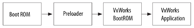
The BootROM is hard coded into the chip and cannot be changed. Upon boot, the BootROM loads the preloader into on-chip RAM, and hands control to it after loading. This BootROM is not the same as the VxWorks BootROM, which is often refered to in the Wind River documentation as “bootrom”.
The second phase of the boot process is the preloader. The preloader completes the initial boot sequence, by setting up the clocks, the external RAM, and the pin configuration of the Altera SoC device. The preloader finishes initial configuration and then loads the VxWorks bootrom into external RAM. It then hands control to the VxWorks bootrom or some other bootloader like u-boot. The preloader can also program the FPGA.
The VxWorks bootrom then loads the VxWorks application into external RAM, and hands control of the system to the final application.
About the VxWorks BootROM and Preloader #
Both the preloader and the VxWorks bootrom can be built from source and must include a header portion that allows the previous boot stage to validate each boot stage. This package contains prebuilt versions of the preloader for the Cyclone V and Arria V SoC development boards that were built using Altera’s SoC EDS environment.
The preloader is typically built by the FPGA designer. This person determines the correct PIN configura‐ tion using Altera’s Quartus and Qsys tools, designs the FPGA portion of the system, and generates the preloader using the preloader Generator, which is part of Altera’s SoC EDS tools.
The VxWorks bootrom is built by a software engineer using Wind River’s development tools. This engineer configures the VxWorks BootROM and builds it in Wind River’s tool, then uses mkimage from Altera’s SoC EDS to put the proper header on the bootrom. For the Cyclone V and Arria V boards, the preloader is board specific and the VxWorks BootROM is not.
The preloader and bootrom are then combined into an SD/MMC image or programmed into QSPI to boot the system.
The Altera SoC EDS tool includes a pre-configured preloader that works with Altera’s development board. Custom boards may require their own preloader configured for their board.
Suggested Ways to Build the VxWorks BootROM #
There are two standard ways of building the VxWorks BootROM:
- Use the Command Line BootROM
- Build a BootROM from a VxWorks Image Project (VIP)
Use the Command Line BootROM #
Build the default bootrom from the BSP.
- Open a VxWorks 6.9 Development Shell from within Workbench.
- In the shell, change to the Wind River install directory.
- Enter
cd vxworks_6.9/target/config/alt_soc_gen5at the prompt. - Build the default bootrom by entering: make bootrom.bin.
For this method, the starting address used with mkimage should be something other than the starting address of the binary. This bootrom uncompresses itself to RAM, so it is best to load it somewhere else in memory so that it can be uncompressed to the starting address. For our testing, we used the value 0x08000040 with mkimage.
Build a BootROM from a VxWorks Image Project #
Create a VxWorks Image Project and build it.
- Create a VxWorks Image Project with the profile PROFILE_BOOTAPP.
- Set the build spec to default_rom.
- Build the
vxworks.bintarget in the project. - Use the
vxWorks_rom.binfile in the default_rom build directory in the project.
For this method, the starting address used with mkimage should be the address shown when you run objdump -f on the vxworks_rom file in the same directory. For our testing, this value is 0x3f000000.
Both of these binaries still need to be wrapped using the mkimage program described in the following sections before they can be used with the preloader.
Both of these binaries properly initialize RAM with boot values so that you can change boot parameters and then use them to start vxWorks.
Custom Preloader Settings Used for VxWorks #
These instructions contain preloaders built from Altera’s SoC EDS tool, version 14.0. You do not have to build the preloader if you plan to use the included binaries, but the source to the preloader and the mkimage program are included in the SoC EDS.
The sofware can be downloaded from the Altera Software Depot webpage using the free web edition.
You can select and download just the SoC EDS. If you plan to program QSPI using the USB Blaster connection on the development board, you may wish to also install the Quartus II Programmer and SignalTap II software.
The pre-built preloaders included in this package work with the Altera development boards. Other boards may require starting with an FPGA design, as described in the HPS Preloader User Guide section of the Altera SoC Embedded Design Suite User Guide.
On Windows, you can get to the preloader code through a windows command shell by starting an Altera command shell from: Start > All Programs > Altera <version> > SoCEmbedded Design Suite (EDS) <version> > SoCEDS 14.0 Command Shell.
This will start a shell with two important variables:
- QUARTUS_ROOTDIR=
'C:\altera\14.0\qprogrammer' - SOCEDS_DEST_ROOT=
C:/altera/14.0/embedded
The preloader is located at $SOCEDS_DEST_ROOT/examples/hardware/cv_soc_devkit_ghrd/software/preloader/.
Related Information
Preloader Changes Made for SD/MMC #
The SD/MMC boot contains two preloader changes. The first change modified the preloader to load the bootloader from the FAT partition of the SD/MMC card rather than the RAW partition. This allows you to store your VxWorks bootrom on the FAT partition. In the second change, the name of the file that is loaded by the preloader is no longer set to u-boot by default. This file name needs to be the name of the VxWorks bootrom, wrapped by mkimage.
The modifications made to the uboot-socfpga/board/altera/socfpga/build.h file are shown below in bolded text:
/* Enable FAT partition support when booting from SDMMC. */
#define CONFIG_PRELOADER_FAT_SUPPORT (1)

/*
 * When FAT partition support is enabled, this specifies the
 * FAT partition where the boot image is located.
 */
#define CONFIG_PRELOADER_FAT_BOOT_PARTITION (1)

/*
 * When FAT partition supported is enabled, this specifies the
 * boot image filename within a FAT partition to be used as
 * fatload payload.
 */
#define CONFIG_PRELOADER_FAT_LOAD_PAYLOAD_NAME "bootloader.bin"
Another change where the preloader loads the FPGA file was made to the uboot-socfpga/include/configs/socfpga_common.h file.
/*
 * FPGA programming support with SPL
 * FPGA RBF file source (with mkimage header) is located within the same
 * boot device which stored the subsequent boot image (U-Boot).
 */

/* enabled program the FPGA */
#define CONFIG_SPL_FPGA_LOAD
Preloader Changes Made for QSPI #
The QSPI boot contains one preloader change. This change made modifications to the preloader to load the VxWorks bootrom from QSPI rather than from the SD/MMC. In another change, the preloader now loads the FPGA. With this change, the preloader now programs the FPGA from a known QSPI address during boot.
The modifications made to the uboot-socfpga/board/altera/socfpga/build.h file are shown below in bolded text:
/*
 * Boot option. 1 means that particular boot mode is selected.
 * Only 1 boot option to be enabled at any time
 */

#define CONFIG_PRELOADER_BOOT_FROM_QSPI	(1)
#define CONFIG_PRELOADER_BOOT_FROM_SDMMC (0)

/*#define CONFIG_PRELOADER_BOOT_FROM_NAND (0)*/
#define CONFIG_PRELOADER_BOOT_FROM_RAM	(0)
Another change where the preloader loads the FPGA file is shown in the uboot-socfpga/include/configs/socfpga_common.h file in bolded text:
/*
 * FPGA programming support with SPL
 * FPGA RBF file source (with mkimage header) is located within the same
 * boot device which stored the subsequent boot image (U-Boot).
 */

 /* enabled program the FPGA */
#define CONFIG_SPL_FPGA_LOAD
/* location of FPGA RBF image within QSPI */
#define CONFIG_SPL_FPGA_QSPI_ADDR (0x800000)
Creating a Bootable Environment Using SD/MMC #
- Set up the board for SD/MMC boot.
With the Altera Cyclone V SoC board oriented so that you can read the Altera Cyclone V SoC logo, set the following jumpers:
- Set jumper BootSEL0: Closed to the right: .[..]
- Set jumper BootSEL1: Closed to the right: .[..]
- Set jumper BootSEL2: Closed to the left: [..].
The sequence for boot selects 0..2 should look like: .[..] .[..] [..].
- Create an SD/MMC card.
Unzip the provided binary file for your development board and use the Win32 Disk Imager program to write it to an SD card. Start from the correct image for your development board:
- sdmmc/av_140_fat_sdmmc.zip for Arria V
- sdmmc/cv_140_fat_sdmmc.zip for Cyclone V
- Load the card into your development board and power up.
- Connect a USB cable between the serial port on the Altera development board and a USB port on your Windows computer. Verify that you see a COM port on your Windows computer.
- Apply power to the development board and connect to the COM port at a baud rate of 115200. Verify that you see the COM port in the Devices and Printers control panel on your Windows computer. You should see the output of the preloader, followed by the output of u-boot. This verifies that you can boot your board with the pre-built image and see serial output.
- The pre-built images include a copy of u-boot that has been renamed to bootloader.bin as a stand-in for your VxWorks bootrom.
- Build the VxWorks Bootrom.
Build your VxWorks bootrom file using Wind River tools and the `alt_soc_gen5` BSP. You can build a command line bootrom, or build a bootrom from a VxWorks Image Project.
For more information on how to build a VxWorks bootrom, contact Wind River or read the BSP documentation.
- Add the Altera header to the VxWorks Bootrom.
Use mkimage to wrap the VxWorks bootrom file with the proper header image. A Windows binary for this tool is included in this package. The mkimage tool is available for linux, as well, but is not included in this package.
This header image contains the address that the preloader uses to load the bootrom. The value 0x08000040 is a good default choice for the compressed bootrom built from the command line. This bootrom will relocate itself to a different area of RAM. Other bootroms may have a different starting address. You can discover the starting address for an ELF version of a bootrom by using this command from a VxWorks development shell:
objdumparm –f <yourfilename>For Windows, use the mkimage program, as shown in the following command, for the default
bootrom.binfile:mkimage.exe -A arm -T firmware -C none -O vxworks -a 0x08000040 - e 0 -n "vxWorks bootloader for SoC FPGA" -d bootrom.bin bootloader.binIn the other files, use an appropriate starting address for the -a option, as determined from the objdumparm command. The mkimage command is similar for Linux, but without the .exe extension.
- Put the VxWorks bootrom on the FAT partition.
- Power off the board, remove the SD/MMC card from the board and put it back in your PC. On Windows, you should see a new removable drive appear.
- Copy the file bootloader.bin created in the previous step to the SD/MMC card, eject the card from the PC, and insert it into the development board.
- Boot the board with the VxWorks Bootrom. Turn on the development board while monitoring the serial port. You should see the preloader boot first, followed by the VxWorks bootrom. You can stop the VxWorks bootrom to change the boot parameters, or allow it to continue to boot.
Related Information
Wind River Board Support Packages
Creating a Bootable Environment for QSPI Using the SD/MMC Card #
First, create a bootable SD/MMC image with u-boot and then use the u-boot to program the VxWorks bootrom into QSPI. This avoids the use of the Altera Quartus programmer, but requires an SD/MMC card instead.
- Perform step 1 - 5 of the Creating a Bootable Environment Using SD/MMC method.
- Rename and copy the VxWorks bootrom to the SD/MMC card.
- On your host system, rename your
bootloader.binfile tovxworksqspi.bin, so that it will not be confused with the bootrom on the SD/MMC card. - Power off the board and remove the SD/MMC card from the board and put it back in the PC. On Windows, you should see a new removable drive appear.
- Copy the file
vxworksqspi.binto the SD/MMC card. - Locate the pre-built QSPI specific preloader binary for your development board. This file is included in this package at:
- Copy your
vxworksqspi.binfile and the appropriatepreloader-mkpimage.binfile to the SD/MMC card. - Eject the card from the PC and insert it into the development board.
qspi/cv/preloader-mkpimage.bin For Cyclone V qspi/av/preloader-mkpimage.bin For Arria V - On your host system, rename your
- Copy the FPGA binary to the SD/MMC card.
The SD FAT partition already includes the correct fpga.rbf file, but it is also included in the instruc‐ tions at:
ghrd_fpga/cv/fpga.rbf For Cyclone V
ghrd_fpga/av/fpga.rbf For Arria V
You must convert this file using
mkimagefor use with QSPI. This is not required when the file is on the SD/MMC FAT partition. In order to do this, you must copy thefpga.rbffile to a directory and run this mkimage command:mkimage -A arm -T firmware -C none -O u-boot -a 0 -e 0 -n "FPGA" – d fpga.rbf fpga.imgWhen done, copy the fpga.img file to the FAT partition on the SD card.
- Use u-boot to program QSPI.
- Turn on the development board and make sure the u-boot booted. The board boots up to a u-boot prompt and stops. Your QSPI preloader and VxWorks bootrom are now on the FAT partition of the SD/MMC card.
- Load the preloader file from the SD/MMC card into a temporary RAM location.
- Partially erase the QSPI flash and program the preloader into QSPI:
% fatload mmc 0:1 0x2000000 preloader-mkpimage.bin % sf probe % sf erase 0x0 0x40000 % sf write 0x2000000 0x0 $filesize - Load the VxWorks bootrom file from the SD/MMC card into a temporary RAM location.
- Partially erase the QSPI flash and program the bootrom into QSPI.
- You must erase on 64K boundaries (rounding up to the boundary past your file size):
% fatload mmc 0:1 0x2000000 vxworksqspi.bin % printenv filesize - Load the FPGA binary from the SD/MMC card into a temporary RAM location.
- Partially erase the QSPI flash and program the FPGA into QSPI.
- You must erase on 64K boundaries (rounding up to the boundary beyond your file size):
% fatload mmc 0:1 0x2000000 fpga.img
% printenv filesize
Note: If the filesize is on a 64K boundary, like 0x40000, you can use that number for the erase command in the next sequence. If not, you must erase up to the next 64K boundary.
For example, if the file size is 0x5a360, you must use the value 0x60000 as the last argument to the erase command. Use this value for
<your-erase-value>in the commands below:% sf probe % sf erase 0x60000 <your-erase-value> % sf write 0x2000000 0x60000 $filesizeNote: Like the last example, you must erase up to the next 64K boundary. For example, if the filesize is 0x5a360, you must use the value 0x60000 as the last argument to the erase command. Use this value for
<your-erase-value>in the commands below:% sf probe % sf erase 0x800000 <your-erase-value> % sf write 0x2000000 0x800000 $filesizeIn the above examples, 0x2000000 is a random RAM location, and can be replaced with any other RAM location that is not in use. The value 0x800000 is the starting address in QSPI for the FPGA image.
- Turn off the development board and remove the SD/MMC card.
- Bootup, monitoring the serial port to see if it worked.
It is OK to leave the card in if you wish, but removing it verifies that you are no longer booting from SD/MMC.
With the Altera Cyclone V SoC board oriented so that you can read the “Altera Cyclone V SoC” logo, set the following jumpers for QSPI boot:
Set jumper BootSEL0: Closed to the right: .[..]
Set jumper BootSEL1: Closed to the left: [..].
Set jumper BootSEL2: Closed to the left: [..].
The entire sequence for boot selects 0..2 should look like: .[..] [..]. [..].
Turn on the development board while monitoring the serial port or connect to it quickly after power- up if the terminal emulator does not allow connecting before power-up. You should see the output of the preloader, followed quickly by the output of the VxWorks bootrom. If you miss these messages, then press the warm reset button to reboot.
Creating a QSPI Bootable Environment with the Quartus Programmer #
If you choose not to create an SD/MMC card, first, in order to boot QSPI, then the Altera quartus_hps programmer can be used with the USB blaster connector to load the preloader and VxWorks bootrom into the QSPI.
For this method, the QSPI preloader from this package and the VxWorks bootrom you created in the previous section are needed. Also the fpga.img file created from the fpga.rbf file in the previous section is needed.
- Collect the files that are needed.
Follow the steps from the Creating a Bootable Environment for QSPI Using the SD/MMC Card section to:
- Create a VxWorks bootrom.
- Wrap the bootrom using the mkimage program.
- Get the correct fpga.rbf file for your board (Cyclone V or Arria V).
- Wrap the fpga.rbf file using the mkimage program to create the fpga.img.
- Get the correct QSPI preloader for your board (Cyclone V or Arria V).
- Create a VxWorks bootrom.
- Set up the board for QSPI boot.
- Get Altera's Quartus II Programmer tool.
- On Windows, create an embedded command shell.
- Connect a USB cable to the USB blaster port.
- Discover your JTAG cable name.
- Program the preloader, VxWorks bootrom and FPGA image into QSPI. Program the preloader file into QSPI:
- Boot up, monitoring the serial port to see if it worked.
After these steps you should have these files:
| File | Description |
|---|---|
| preloader-mkpimage.bin | The QSPI preloader from this package for your board. |
| fpga.img | The fpga.rbf from this package, wrapped with mkimage. |
| vxworksqspi.bin | The VxWorks bootrom you built, wrapped with mkimage. |
With the Altera Cyclone V SoC board oriented so that you can read the “Altera Cyclone V SoC” logo, set the following jumpers for QSPI boot:
Set jumper BootSEL0: Closed to the right: .[..]
Set jumper BootSEL1: Closed to the left: [..].
Set jumper BootSEL2: Closed to the left: [..].
The entire sequence for boot selects 0..2 should look like: .[..] [..]. [..].
For more information on how to download and install version 14.0 of Altera’s Quartus Programmer tool, navigate to the Quartus II Programmer and SignalTap II install under the Additional Software tab on Altera’s Software Depot website.
Start an Altera command shell from Start > All Programs > Altera <version> > SoC Embedded Design Suite (EDS) <version> > SoC EDS 14.0 Command Shell.
This will start a shell with two important variables:
QUARTUS_ROOTDIR='C:\altera\14.0\qprogrammer'
SOCEDS_DEST_ROOT=C:/altera/14.0/embedded
Connect a USB cable from a USB port on your Windows PC to the port labeled “USB Blaster” on the board to be programmed.
From your embedded command shell, power on your board and run the jtagconfig command.
1) USB-BlasterII [USB-1] 4BA00477 SOCVHPS
02D020DD 5CS(EBA6ES|XFC6C6ES)/..
020A40DD 5M(1270ZF324|2210Z)/EPM2210
In this example, the cable is 1. Use this value for all calls to quartus_hps as the parameter
quartus_hps -c <cable> -o P -a 0 -s 0x40000 preloader-mkpimage.bin
Program the VxWorks bootrom into QSPI at address 0x60000. This address is from the preloader build.h file in the define CONFIG_PRELOADER_QSPI_NEXT_BOOT_IMAGE:
quartus_hps -c <cable> -o P -a 0x60000 vxworksqspi.bin
Program the FPGA image file into QSPI at address 0x800000. This address is from the preloader socfpga_common.h file in the define CONFIG_SPL_FPGA_QSPI_ADDR:
quartus_hps -c <cable> -o P -a 0x800000 fpga.img
After programming these files, it is important to remove power from the board for about ten seconds. The user may see a CRC error upon load if the board is not powered down for enough time. This can be resolved by removing power, waiting, and trying again.
Turn on the development board while monitoring the serial port at 115200 baud. You should see the output of the preloader, followed by the output of the VxWorks bootrom.
Related Information
Configuring VxWorks using the Bootloader #
From the VxWorks bootlooader, you can use the p command to print the boot settings and the c command to change them. The M command can be used to change the MAC address of the emac1 port.
Configuring for Boot with the VxWorks Image on an FTP Server #
Use the following boot parameters:
Table 1: Boot Parameters
| Parameter | Value |
|---|---|
| boot device | emac1 |
| unit number | 1 |
| processor number | 0 |
| host name | host |
| file name | C:/WindRiver/vxworks-6.9/target/config/alt_soc_gen5/vxWorks |
| inet on ethernet (e) | 192.168.1.2:ffffff00 |
| host inet (h) | 192.168.1.20 |
| gateway inet (g) | 192.168.1.1 |
| user (u) | target |
| ftp password (pw) | vxTarget |
| flags (f) | 0x0 |
| target name (tn) | alt_soc_gen5 |
| other (o) | - |
For Ethernet boot, the “inet on Ethernet” address should be a static IP address assigned to the board. The hex code after the address is a network mask. The “host inet” address is the address of the machine with the VxWorks application.
Most developers use Ethernet boot when developing code, then copy their code to the SD card for booting without using a host.
Configuring for Boot with the VxWorks Image on the SD Card FAT Partition #
VxWorks can also be booted from the FAT partition on the SD/MMC card. To do so, edit the config.h file in the BSP directory to add the following options:
/* Add this to end of config.h to boot vxworks from the SD flash file system */ #define DRV_STORAGE_ALT_SOC_GEN5_DW_MSHC
#define INCLUDE_BOOT_FILESYSTEMS
#define INCLUDE_DOSFS
Next:
- Build
bootrom.binfrom a VxWorks development shell. - Use
mkimage.exeto create thebootloader.binfile as described inStep 5of the Creating a Bootable Environment Using SD/MMC section. - Copy the
bootloader.binand yourVxWorksimage to the FAT partition of your SD card.
Use the following boot parameters listed in the following table:
Table 2: Boot Parameters
| Parameter | Value |
|---|---|
| boot device | fs |
| unit number | 0 |
| processor number | 0 |
| host name | host |
| file name | /sd0:1/vxWorks |
| inet on ethernet (e) | 192.168.1.2:ffffff00 |
| host inet (h) | 192.168.1.20 |
| gateway inet (g) | 192.168.1.1 |
| user (u) | target |
| ftp password (pw) | vxTarget |
| flags (f) | 0x0 |
| target name (tn) | alt_soc_gen5 |
| other (o) | emac1 |
Optionally, specifying “emac1” in the other field, will configure and enable the Ethernet port even though it is not actually booting over Ethernet. The VxWorks BSP target.ref file has more information on SD support.
This boot method cannot be used in conjunction with the boot method in the following DHCP section.
Configuring for Boot Using DHCP and FTP #
VxWorks can also use DHCP to get an IP address before retrieving the VxWorks image via FTP. To do so, edit the config.h file in the BSP directory to add the following options:
/* Add this to end of config.h to boot vxworks using DHCP */
#define INCLUDE_BOOT_DHCPC
#define INCLUDE_IPDHCPC
#define DHCPC_OPTION_MAX_MESSAGE_SIZE "576"
#define DHCPC_TTL "1"
#define DHCPC_FLAGS_BIT_BROADCAST "0"
#define DHCPC_IF_INFORMATION_ONLY_LIST ""
#define INCLUDE_IPNET_IFCONFIG_1
#define IFCONFIG_1 \
"ifname","devname driver","inet dhcp","gateway dhcp","inet6 3ffe:1:2:3::4/64"
Next:
- Build bootrom.bin from a VxWorks development shell.
- Use mkimage.exe to create the bootloader.bin file as described in Step 5 in the Creating a Bootable Environment Using SD/MMC section.
- Copy the bootloader.bin and your VxWorks image to the FAT partition of your SD card.
Uset the following boot parameters:
Table 3: Boot Parameters
| Parameter | Value |
|---|---|
| boot device | emac1 |
| unit number | 1 |
| processor number | 0 |
| host name | host |
| file name | C:/WindRiver/vxworks-6.9/target/config/alt_soc_gen5/vxWorks |
| inet on ethernet (e) | - |
| host inet (h) | 192.168.1.20 |
| gateway inet (g) | 192.168.1.1 |
| user (u) | target |
| ftp password (pw) | vxTarget |
| flags (f) | 0x40 |
| target name (tn) | alt_soc_gen5 |
| other (o) | - |
This boot method cannot be used in conjunction wit the boot method in the previous SD section.
Sample Images #
This package comes with prebuilt images that have been tested with the development boards.
The ghrd_fpga directory contains FPGA binaries for the Altera Golden Hardware Reference Design:
- av - contains the GHRD binary for the Arria V SoC product
- cv - contains the GHRD binary for the Cyclone V SoC product
The qspi and sdmmc directories each contain subdirectories for each target board:
- av - support for the Arria V SoC development board
- cv - support for the Cyclone V SoC development board
Each of the av and cv directories contains preloader (spl) code specific to qspi or sdmmc:
- u-boot-spl - an ELF version of the preloader that can be used with DS-5 Altera Edition
- u-boot-spl.bin - the preloader
- u-boot-spl.map - a map file for the preloader
- preloader-mkpimage.bin - the four-copy preloader with the proper header image
The sdmmc directory additionally contains these files:
- make_sdimage.sh - a Linux script for creating SD/MMC images
- av_140_fat_sdmmc.zip - a prebuilt SD/MMC image for the Arria V board
- cv_140_fat_sdmmc.zip - a prebuild SD/MMC image for the Cyclone V board
The sample SD/MMC images were created on a Linux system, running as root, using the following command:
./make_sdimage.sh -p preloader-mkpimage.bin -b u-boot.img –k bootloader.bin,u-boot.img,fpga.rbf,readme.txt –o cv_140_fat_sdmmc.img -g 512M
The preloader and FPGA files were built specifically for the development board and are different between Cyclone V and Arria V. The u-boot.img file included on the RAW partition is not used and is just there to satisfy the make_sdimage.sh script. The preloader is configured to boot the file bootloader.bin on the FAT partition. For SD/MMC, the preloader loads the fpga.rbf file from the FAT partition on the SD card. The SD card images include a version of u-boot that can be used to program the QSPI.
Other Resources #
For more Altera documentation, you can visit the Altera SoC Embedded Software Tools documentation page and the Altera SoC Embedded Design Suite User Guide.
For more information on using Linux with the Altera SoC or how to set up the development board, refer to the Rocketboards website.
Related Information